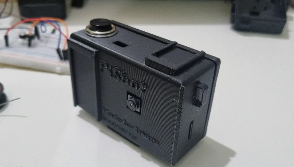
I Made a Custom Raspberry Pi Camera - Journal: PiShot
This is my complete journey of making a custom Raspberry Pi camera: PiShot.
I made it with a Raspberry Pi Zero 2 W, a Pi camera module, and a custom 3D-printed case.
This project is open-source, and you can check it out here!
I also made a showcase video for it!
Total time spent: ~43.5 hours!
Design + Firmware
Time spent on design: ~19 hours
July 25th: Research + Wiring Diagram
The plan is to make a Camera with a custom 3D case (with a tripod, grip, and viewfinder), using the Raspberry Pi Zero 2W, and the Pi camera module 3, and the ST7789 LCD, that stores the photos on an SD card, and you can view the last photo (and explore all the shoots) on the display!! It will be in the Cyber-shot form factor!!
Started by looking up all the different Pi Camera modules and comparing their results! Settled on the Camera module 3, as it has auto focus! I will be using the Pi Zero 2W as the MCU, as it is the lowest-performance MCU that supports the camera. Then I made a list of all the components I would need! I decided to go with a 1500mAh 3.7V LiPo battery with an MT3608 boost converter, and a TP4056 module (with protection) to charge it! (At first, I was considering a power bank or an 18650 cell, but those are too bulky!) For the display, I will be using the ST7789 TFT-LCD. And a metal momentary push button (similar to this, but without the LED ring!) for the shutter button! And I will also place an SPDT slide switch to turn it on and off!
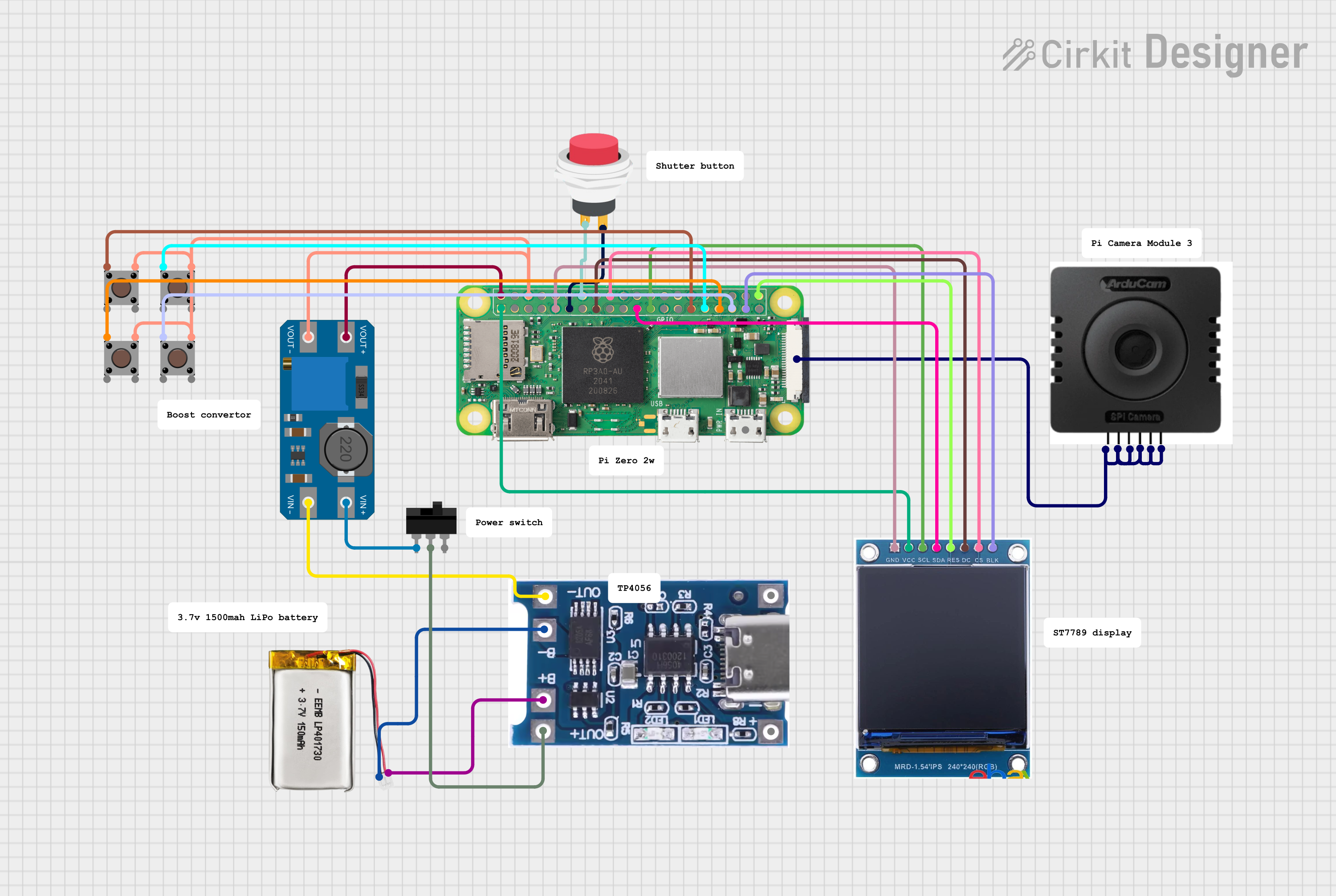
I decided that I won’t be using a PCB, so it’s easier to place all the components in the case. So I will make a wiring diagram instead! Thus, I opened up Cirkit Designer, and got to work!! This is what I came up with!
Total time spent: 3.5 hours
July 26th: Started 3D Case Design
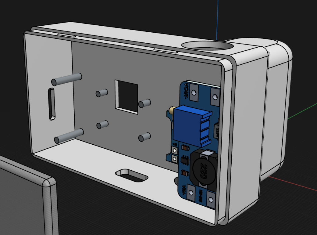
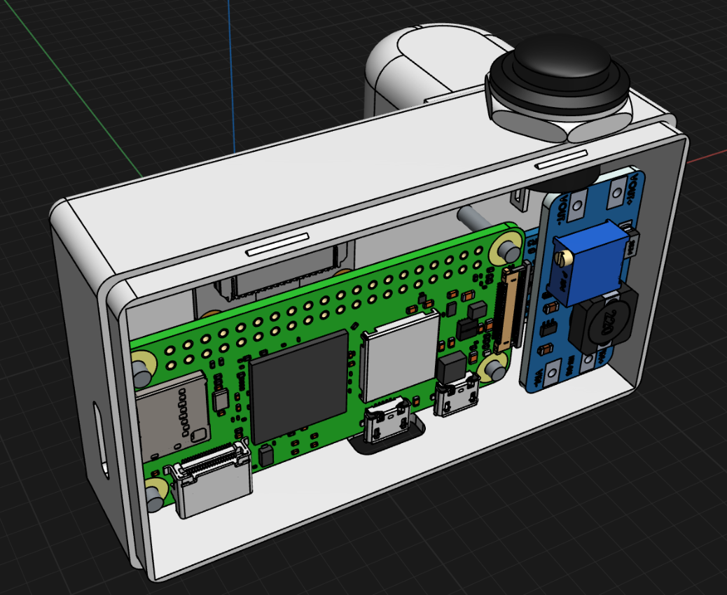
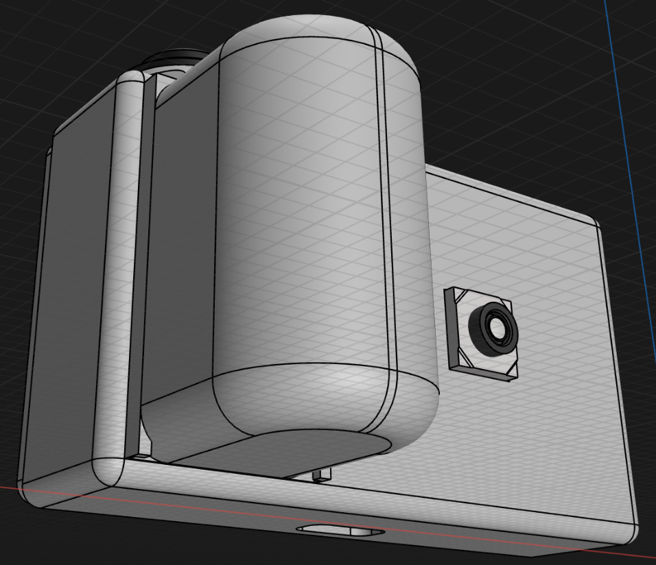
I began by finding and downloading 3D models of all the components I would be using. This process took a significant amount of time, as I had to search extensively to locate every part! After that, I started designing the case in Shapr3D on my iPad. I first created a rectangular base for the body, including a removable back. Next, I added a square hole in the centre for the camera module, and a hole at the top for the shutter button. The challenging part was designing a grip that could slide into the case and be removed easily. Developing the sliding mechanism took quite a while, but I think it turned out pretty cool!
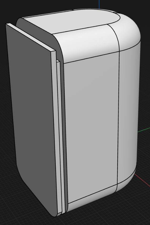
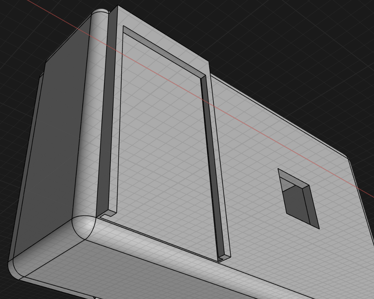
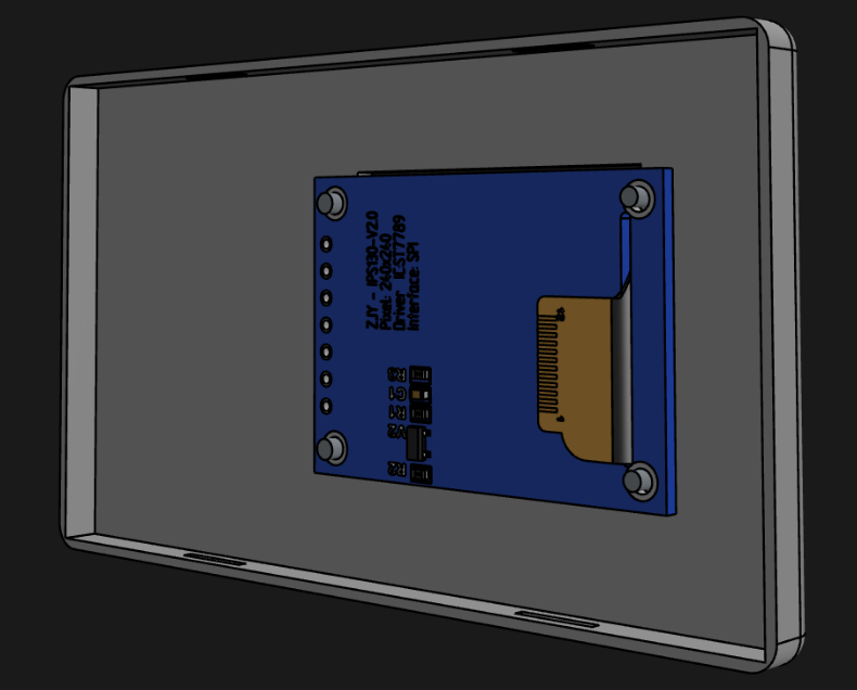
I began by placing each component into the interior of the case, ensuring that they were properly secured. I created holes on the sides and bottom for the SD card and the USB port of the Raspberry Pi. I also made an opening in the back cover for the LCD screen and added supports for all the components. However, I did not create a hole for the USB-C port, as I was still unsure about where to place it.
Total time spent: 7 hours
July 27th: Buttons + USB C Port + TP4056 Supports
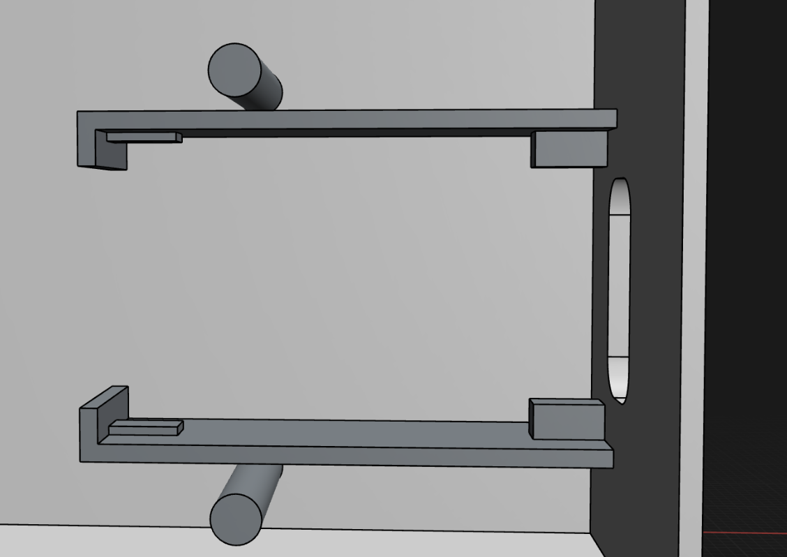
Looked through the datasheet for these circle micro pushbuttons and noted their size, then made a cool to-size slot for them in the case!
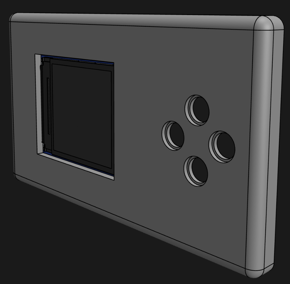
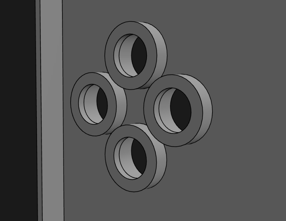
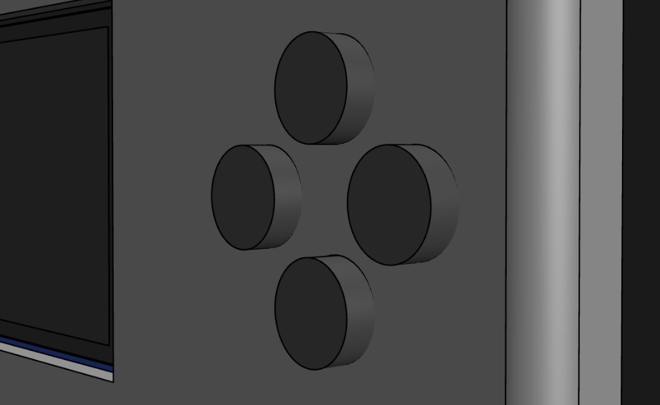
Then, I also made a slot for the USB-C port, and some supports for the TP4056!
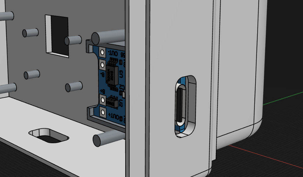
Total time spent: 2 hours
July 28th: Tripod + Viewfinder
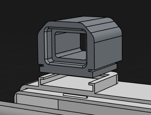
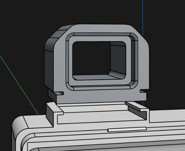
Inspired by the removable Sony viewfinder, I also decided to make one too! It will also have a sliding mechanism like the grip! I started by making an extrusion and adding the sliding mechanism, then I made a separate rectangle body, with a rectangle hole in the middle (this will be the viewfinder). I then fillet/chamfered it to look more trapezium-ish, like a real viewfinder. And finally, I also added some nice rounded supports to rest the eye on! These were the final results!!
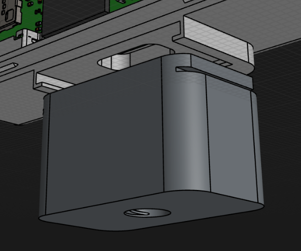
Then I thought about adding support for standard tripods! And, of course, I think the sliding mechanism is super cool, so I built another bit of it on the bottom of the case, and then made a cube with a screw hole in it! Thankfully, I discovered Shapr3D’s subtract tool, or I don’t think I could have ever made the screw curve paths!! And finally rounded off the edges to make it look more polished!
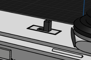
Then I remembered I had forgotten to add space for the SPDT On/Off switch, so I added that!
Total time spent: 3 hours
July 29th: Finished Design
The only thing left now was some final polishing- wait, I forgot to make space for a rechargeable battery!! So I imported a model of an 18650 cell, and tried to make space for it! But I couldn’t :(. So finally I split my case (front, back, grip, everything) into two parts, increased its height by 5mm, and then joined it once again! So now my case was 5mm taller, and I could fit the battery inside too! And then I had to move around all the slots like front buttons, screen, camera hole, etc, around to centre them again and make them look nice!
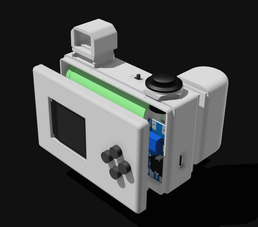
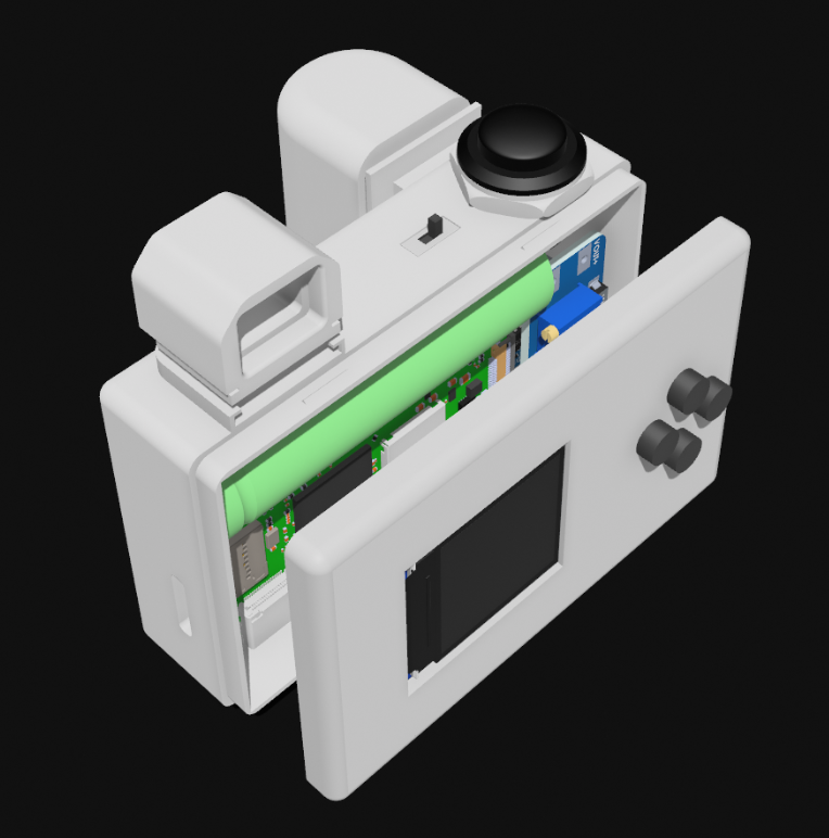
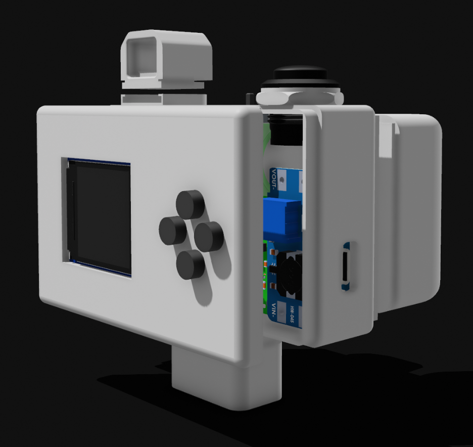
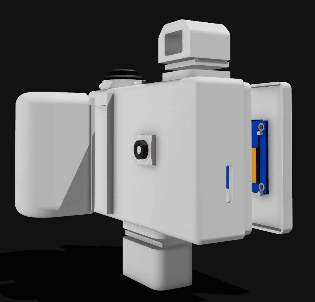
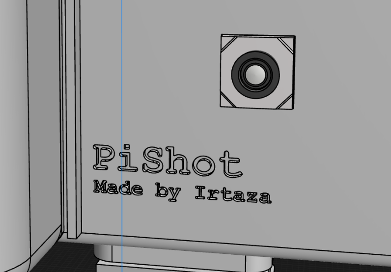
And then I also added some text to the front of the camera, for personalisation!
Final 3D design!!
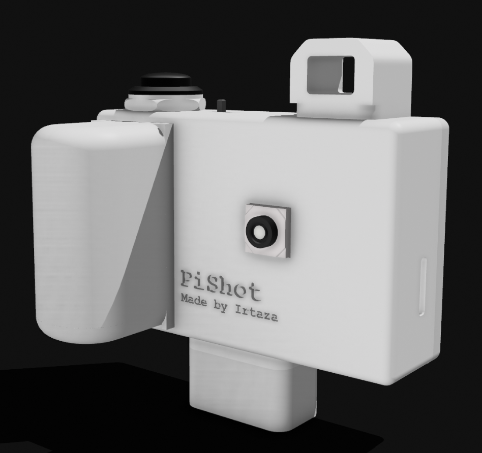
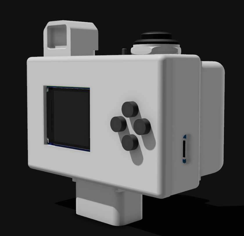
Total time spent: 2.5 hours
July 30th: Made Firmware
Got to work on coding the firmware for the Pi! I have never before used a Pi Zero 2w, but it was super easy to code for it because, well, it’s a full Linux computer! So no flashing or stuff, I just have to make a Python file and add it to run on boot!
Right now, I randomly assigned the GPIO pins in the code because I don’t know what pin I might end up using for what. The script should will: display a splash screen, wait for shutter button press, capture image from camera, and save it to SD card with a timestamped filename!
Total time spent: 1 hour
IRL Building!!
Time spent on soldering/building: ~24.5 hours
August 20th: Finished Building Prototype
All of the parts arrived today except for the Pi Zero W camera ribbon cable and the 3D case. So I decided to start and make a breadboard prototype to make sure everything works, and also just to make everything with the camera functionality, so I only need to connect the camera when the cable arrives!
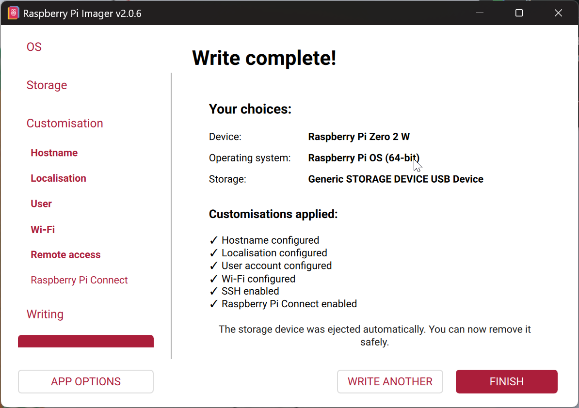
First, I flashed an SD card with Pi OS, with SSH enabled, and put that into the Pi Zero 2W! Then I SSHed into it! And it was really fun! I might even have got lost playing with all the different settings and testing out the different RPi features like RPi connect c:! The interface was interesting! Then I used nano for the first time to code, and it was pretty easy to use after learning the shortcuts (though selection is pretty hard).
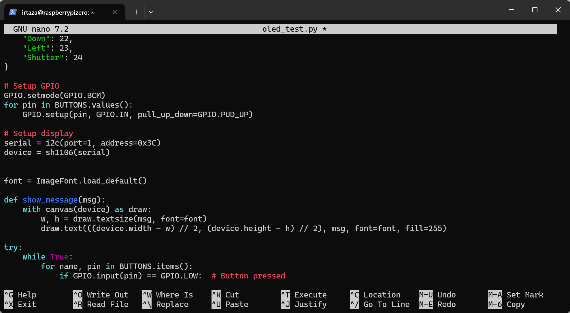
After that, I looked up the pin layout for the Pi Zero 2 W, attached my shutter and pushbuttons, and my OLED. The buttons worked fine, but it took a lot of time to make the LED work! And after a lot of going back and forth, debugging the LED, I found out that it was not a 128x64 SSD1306, but a 132x64 SH1106. So I downloaded its libraries, updated my code, and it started working!
Then I brought out my soldering iron and got to work soldering the power components! I think everything was correctly set up, but I didn’t connect it to the Pi just yet, because I don’t know what output voltage the MT3608 is set to, as I don’t have a multimeter, and don’t want to fry my Pi Zero 2 W.
Now I just have to wait for the Pi Zero 2 W camera ribbon cable to arrive!!
Total time spent: 4.5 hours
The parts took a lot of time to arrive, so I didn’t get to work on the project for a while. But now that they have arrived, I can finally continue working on it! So 6 months later…
February 7th: Case Revisions
Worked on the case again! Improved the sliding mechanism, and took tolerance into account this time so it wouldn’t be so tight. Also added little holes on each side of the case for a lanyard/keychain!
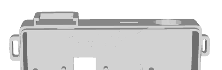
And updated all the text planes, going for 0.2mm minimum extrusions and intrusions this time!
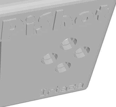
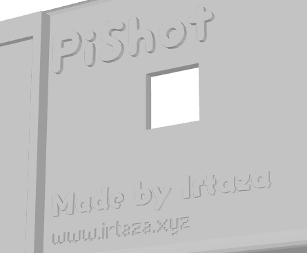
Total time spent: 2 hours
February 9th: First Breadboard Prototype
Got out all the components I would need and made a basic breadboard prototype! Ran the Python script on the Pi, and it worked!
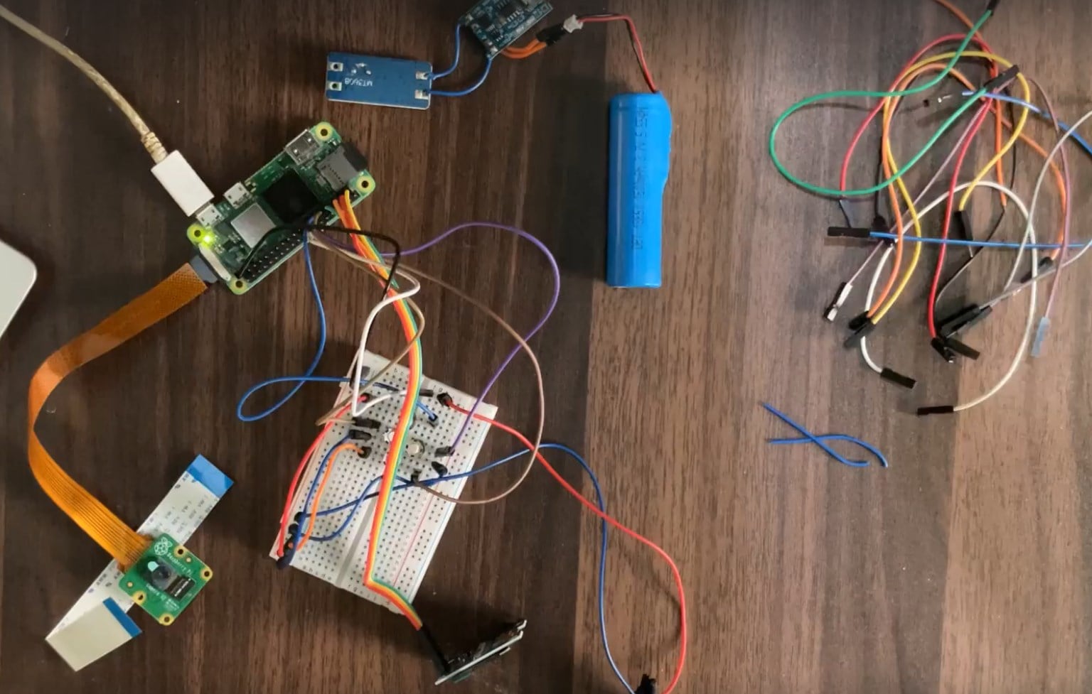
I didn’t include the LiPo and the charging module for this — it’s directly powered through USB for now. Will wire that up next! Here are some pictures I took with the camera:


Now I am going to solder it all together, and wire the power components next!
Total time spent: 4 hours
February 9th (later): Charging Module Won’t Cooperate
Soldered the LiPo to the TP4056, and that to the boost converter (MT3608), but it doesn’t work. Tested both modules with a multimeter, but I can’t read any voltage. The LiPo is charged, so I think the TP4056 might be defective. Also tried powering the charging module with a USB cable, but it doesn’t light up. Even tried replacing it with another one (I bought 2 TP4056s from the same place), but that one also doesn’t work.
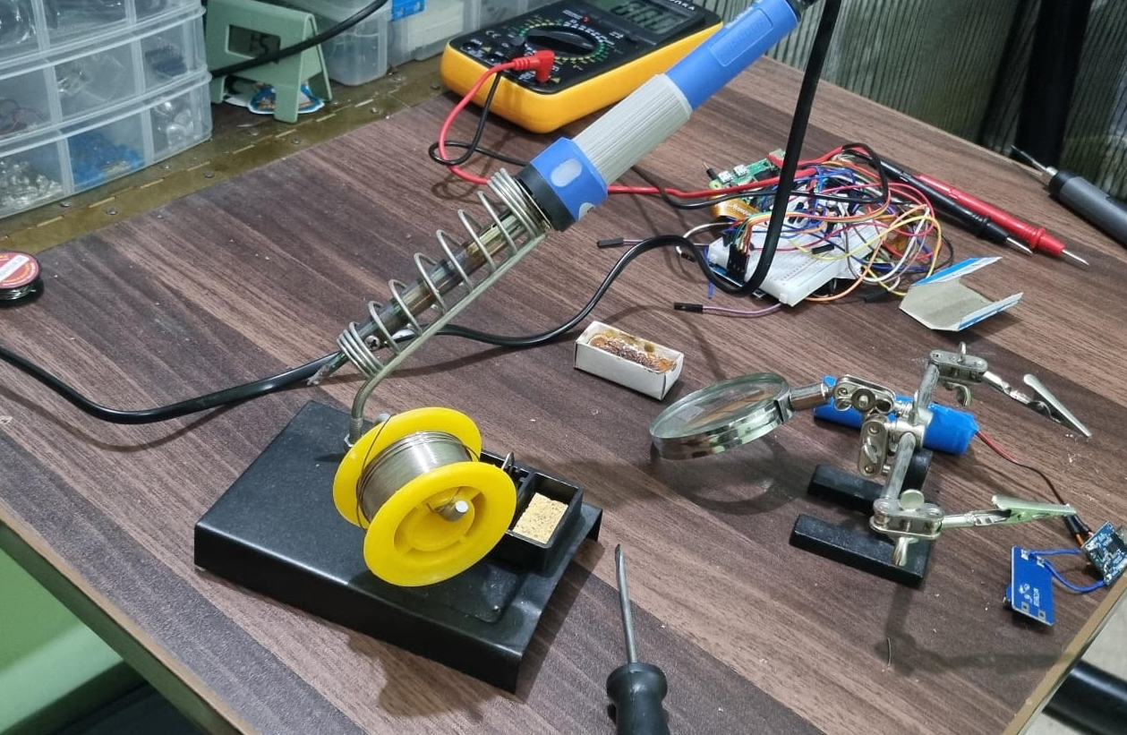
Ordered new ones and will wait for them to arrive. That’s it for today, will assemble the camera without the power bit tomorrow, or work on the case instead!
Total time spent: 2.5 hours
February 12th: Rebuilding the Power Circuit
Finally got the new TP4056 and MT3608 modules delivered today! Removed all the solder and wires from the previous components, and wired the new TP4056!
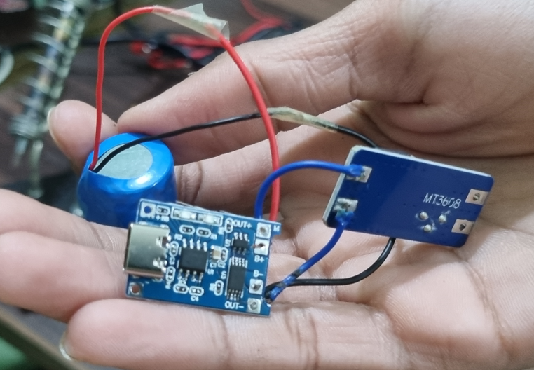
And it worked!
However, when I moved the components around to test the MT3608 boost converter, all of the wires came apart. So I started from scratch again, this time using some longer wires (cut up from some jumper wires I had).
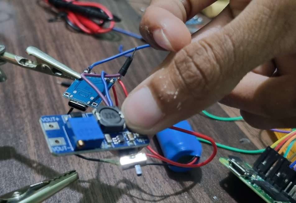
This time, the solder held! So I brought out my multimeter to set the boost converter to the right voltage (5.1V for the Pi). But it refused to go above 4V, no matter how much I rotated the potentiometer.
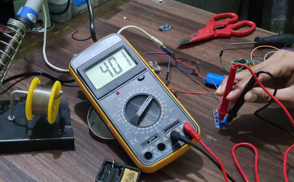
So I decided to replace the MT3608 with a new one, testing it before soldering this time, and it showed a greater voltage. Completed wiring it all together, and successfully set it to 5.1V!!
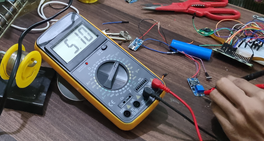
Also added a switch between the TP4056 and MT3608, which will act as the main power switch for the camera!! Next, I’m going to wire this module to the Pi Zero 2W, and hopefully it will work!! Most of my time today was spent soldering, then unsoldering, then resoldering — I’m starting to hate soldering 😭!
Total time spent: 4 hours
February 16th: Revising the Case After the First Print
Printed the 3D models I had made!
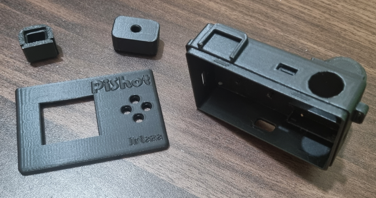
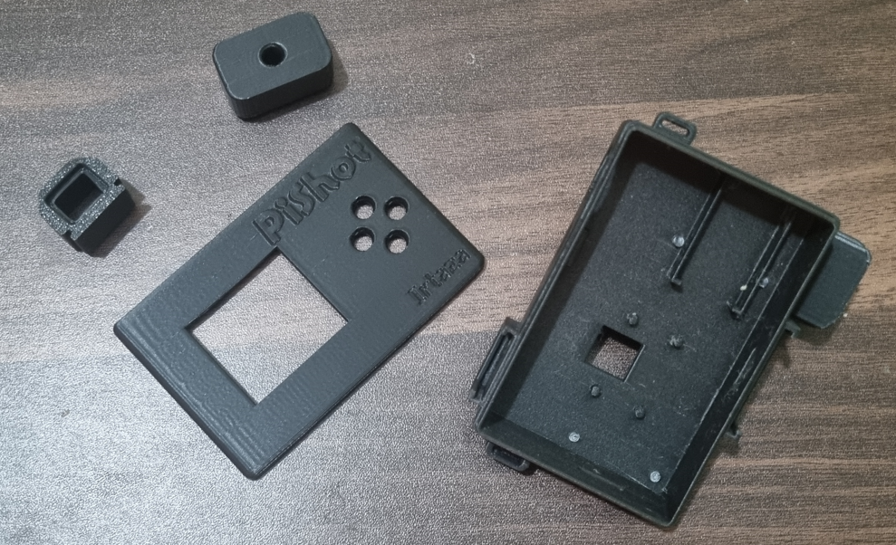
The sliding mechanisms for the viewfinder and grip worked, but were a bit tight, so I decided to sand them. Tried fitting all the components inside, but sadly the LiPo is a bit big, and the Pi Zero 2W and camera module don’t fit perfectly in their slots. So I took some measurements (with a ruler — I don’t have a calliper) and edited the 3D models!
First, I increased the depth, to make some space for wires and stuff.
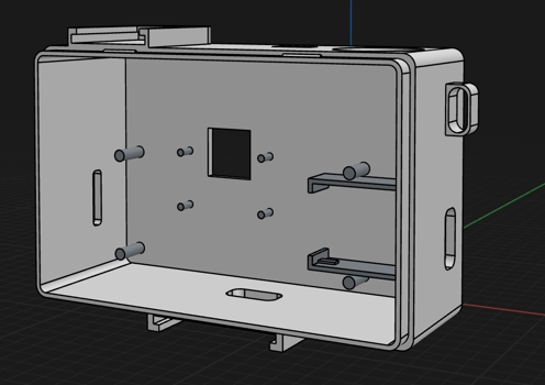
Then I reduced the size of the sliding mechanism to make it work without sanding, since I was printing another revision anyway.
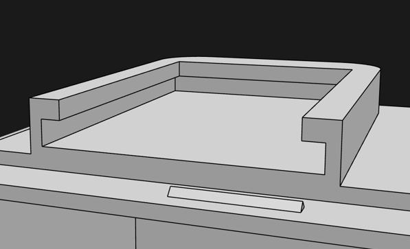
I also increased the size of the keychain holes, because they were too small.
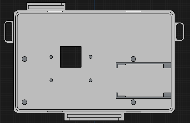
Made sure only the main body was affected by these changes, and not any of the attachable stuff, so I won’t have to reprint that. Now time to wait for the new print!!
Total time spent: 2.5 hours
February 20th: Everything Fits in the New Case
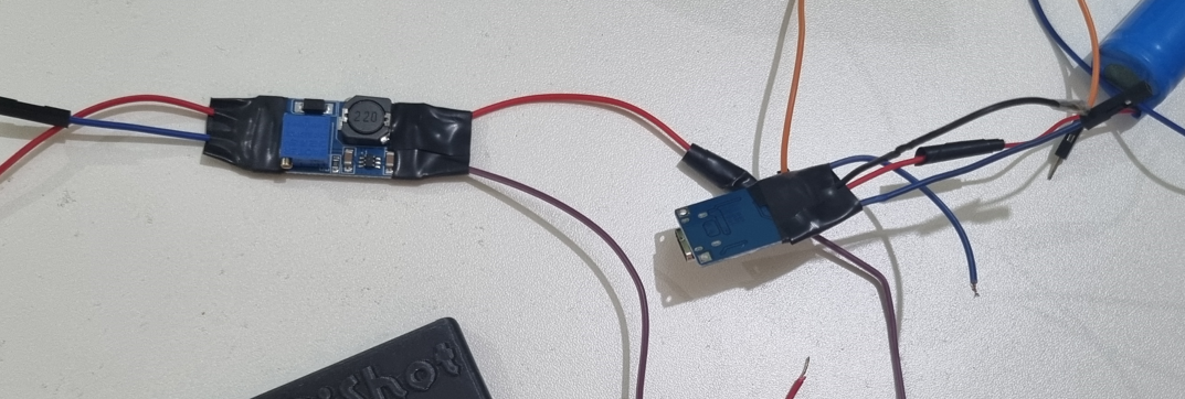
Printed the new case!! Also, the bits I had soldered seemed to be coming off, so I taped them down with electrical tape too.
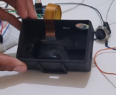
Then I started placing everything in the new case! (And used some tape to hold stuff down.)
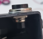
And everything fit perfectly! The shutter button even screwed into place.
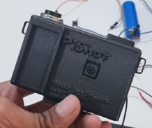
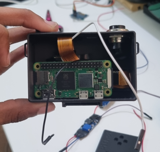
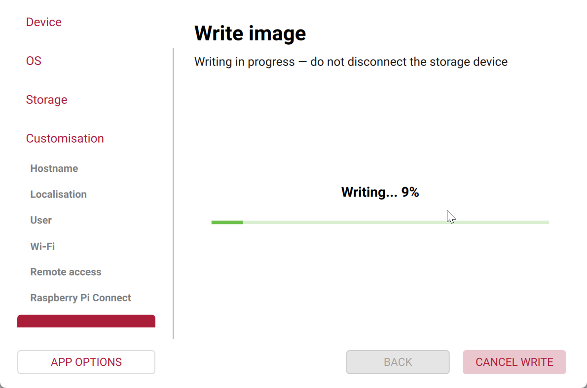
Now I’m flashing an SD card with Pi OS for the Pi Zero 2W, since I lost the previous card, and then I’ll test out the camera!!
Total time spent: 2.5 hours
February 20th (later): It’s Alive!
Flashed the SD card with Pi OS!
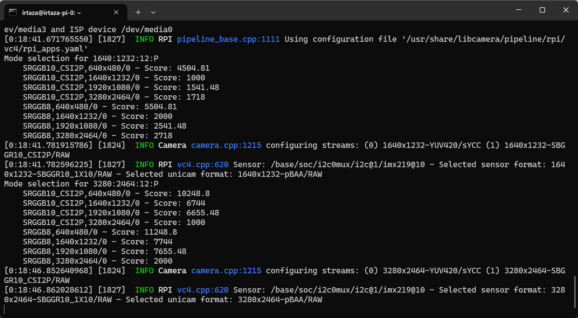
Then I added the script, and after a bit of debugging, swapping and installing different libraries, the script worked!
However, the shutter button was a bit buggy, so I also wired a small button too!
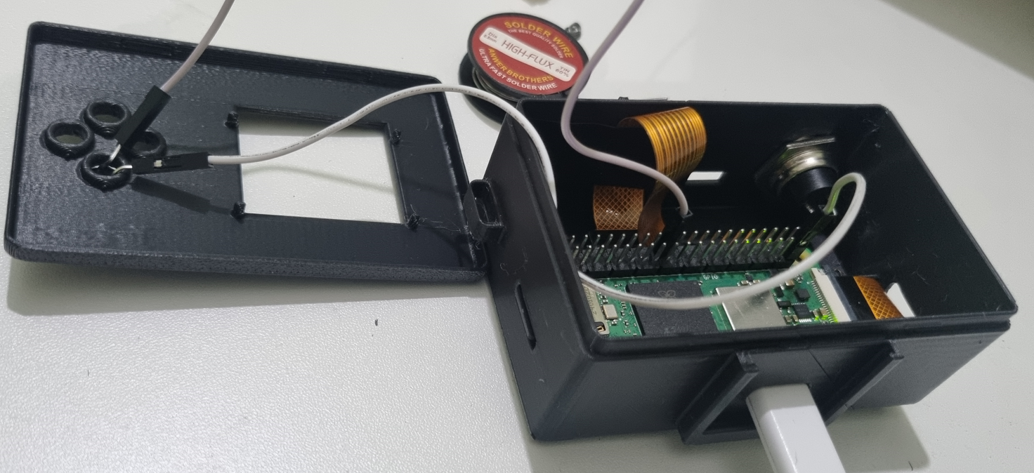
And now I have my completed camera!!
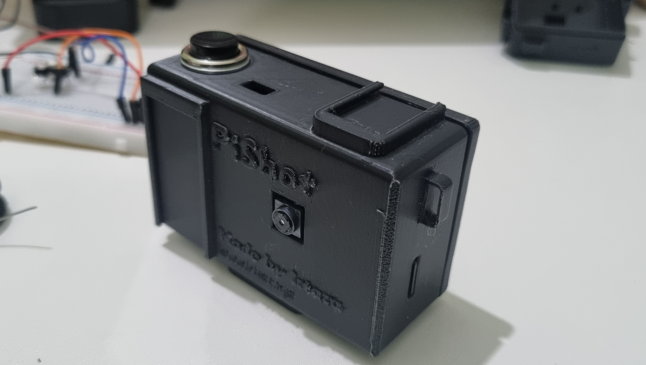
And it works!!! Here are some of the pictures I captured using it!!
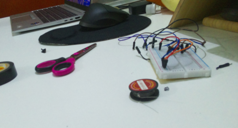
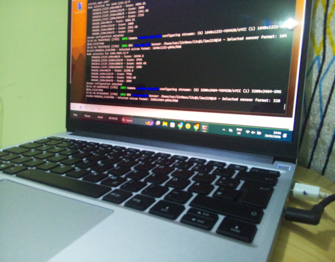
Total time spent: 2.5 hours
And that’s it!
My completed custom Raspberry Pi camera, PiShot!
It was a fun journey, and I learned a lot about 3D design, soldering, and coding for the Raspberry Pi.
And btw, this project is open-source, so you can check out the source code or 3D files here!
I also made a short showcase video for the camera!
I hope you enjoyed reading about my process as much as I enjoyed making it! (was kind of a long read, sorry!!)